Tuesday, June 11, 2013

Cloud Chamber Project

Purpose
The purpose of this project is to build a cloud chamber, which can be used as an apparatus to track particles such as alpha, beta, and muons.

PRET Chart


Bill of Materials
The only material we have to buy is the dry ice.
$10 for every time we run the experiment.

Criteria for Success

1. We can observe the formation of cloud inside the chamber.
2. The cloud bends under the influence of magnetic field.
3. We can collect data to compare to published values.

5/10 (week 1)

We were trying to design the chamber. Initially, we used a petri dish because it has a greater surface area, so it is more obvious for us to observe the cloud. Also, the volume of a petri dish is small, so it takes shorter time for the alcohol to evaporate.
This is our initial design of chamber because we had not gotten the radioactive emitter from prof mason at this time, so we did not really know if the emitter was going to fit into this chamber or not.
Finally we got the emitter, and it was broke down from a smog detector.
 
the emitter did not fit the petri dish.
 
Here is our second design:
 
But the problem is:
beaker has an openning part, so the alcohol will leake out.
 
With those problems fixed, this is what we use during the whole project
Electrical tape was used to seal around the lid to avoid leakage of alcohol.
 
5/24 (week 3)
 
Materials used

 
Experimental setups:

without magnetic field
with magnetic field
Results

without magnetic field
with magnetic field 
 
Summary:
We can see some clounds, but it is not that obvious. Therefore, our next week job will be reproduce the same cloud and how to make it obvious.
 
5/31 (week 4)
 
Following the same method, but we got a lot of mist and cloud at the bottom and no clouds. After doing research, we knew that it is because 1) we put way much more alcohol inside. 2) there is a lekage of alcohol on the bottom. We decide to work on it tomorrow.
 
6/1 (week 5)
Because the cloud chamber needs supersatured alcohol, I put a lot of them before, and we ended up with the a huge amount of mist inside the chamber and also some clouds on the bottom due to the leakage of the alcohol. Therefore, this week, I add alcohol to the felt inside the chamber until it start drips when I invert the bottle and then take those excess (dripped) amount of alcohol out and tape the lid. Furthermore, in order to make the cloud more obvious, we put a warm bag on the top of the bottle, accelerating the evaporation of alcohol.
 Final results
 
without magnetic field
with magnetic field
 
Now we successfully made more clouds and the bending under magnetic field is more obvious.
 
Data
we count the number of particles per minute for 10 minutes


Errors and uncertainties
The experimental value does not agree with the published data. In the cloud chamber, not just americium decay was observed but also the cosmic rays such as muons and neutrinos. Also, the theoretical value is in the 10^6 order, we cannot count that much particle per minute with human eyes because there were multiple clouds formed at every second, but we can only catch as many as possible. Through the project, there were some alcohol leakage even after we modified it with electrical tape, thus resulting the reduced amount of clouds observed. Also, the chamber we used has a lid with it, so some amount of alcohol vapor was condensed on the lid, causing the reduced alcohol vapor for condensation. The temperature gradient is also an important factor for the success of the cloud chamber. The differences of temperatures on the two sides of the chamber should be significant. The dry ice is cool enough on the bottom side, but the lid is a insulator, making our chamber not cold enough. Also, when we put a warm bag on the top, the glass will insulate the chamber from the heat, too. Therefore, the future work could be looking for materials that can condut heat well, and use that material to build the chamber.
 
The copy of our powerpoint slides are available at:


Monday, May 27, 2013

5/20 Planck's Constant from an LED

Purpose
The purpose of this experiment is to determine the planck's constant by measuring the ranges of light emitted by different colored LEDs through a diffraction grating.

Experiment
Set up
 
Set up
 
Red LED
 
Green LED
Blue LED
Yellow LED 
White LED
If the LED doesn't glow, then swithch the polarity of the LED. This is because the depletion region is getting larger, it becomes a resistor. If switch the polarity, then the depletion region is getting smaller, so the current can pass through. 
Data Analysis and Graphs
 
 
This slope was used to determine h
 
This slope was used to determine h max.
 Average planck's constant:
color light
wavelength(nm)
voltage(V)
h (Js)
error(%)
red
606.82
1.89
6.12E-34
7.74
green
513.74
2.58
7.07E-34
6.58
yellow
570.066
1.92
5.75E-34
13.2
blue
456.08
2.65
6.46E-34
2.63
Average
6.35E-34
4.26
 
Questions
As looking through the spectroscope for each of the LED as to colors displayed on the scale, they are all one color instead of a mixture. The white LED gives a mixture of colors because white light reflects all colors of light. The yellow LED gives the largest error. According to the data table, the wavelengh decreases as the potential increases.  The atmosphere scatters blue better than red because blue light has a higher frequency, but the red light has lower frequency, it is trapped or concentrated in the direction of the sun.
Conclusion
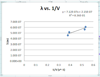
From the graph of lamda vs. 1/V, the plank's constant was determined to be 4.27*10^(-34) ± 0.54*10^(-34) Js, with a percent error of 33%± 5%. The theoretical value of plank constant, 6.63*10^(-34) Js does not lie within the uncertainty of our experimental data. However, the experimental plank constant determind from the formula, h= lamda (ev)/ c to be 6.35+/- 0.72 *10^(-34) Js, with a percent error of 0.16%. Therefore, the theoretical plank constant lies within the range of the h with uncertainty. The possible reason that why the h determined from the graph has a larger percent error is related the best-fit line. The R^2 value is 0.827 instead of 1, so some of our data points are not in this line, thus the h determined form the slope is not accurate.


5/15 Color and Spectra

Purpose
The purpose of this experiment is to determine a calibration graph of wavelength using the white light, determine the experimental wavelengths of the four hydrogen lines through a diffration grating, compare the theoretical wavelengths of the four hydrogen lines to the calibrated wavelengths for hydrogen atom.

Experiment
Set up: white light source
 
Set up: white light source
Spectra observed through a diffraction grating
derivation of λ = Dd/(L2+D2)
 
measurements and calculation of wavelengths
a calibration function was determined.
spectra of a hygrogen gas
 
spectra of a hydrogen gas
 
calculating experimental wavelengths
 
calibrated wavelengths vs. theoretical wavelengths
 
 
Experimental calibrated wavelength (nm)
Theoretical wavelength (nm)
423±25
410
490±14
486
680±27
656
 
Conclusion
The four hydrogen lines are red, green, blue, and purple. In our experiment, red, green, and purple are observed. The blue light is not observed because the purple and teal light next to the blue are really light, so we did not see the blue. Ohter than the blue light, all the other three colors are observed, and the experimental wavelengths determined (calibrated) lies within the uncertainty range of the theoretical walengths calculated from the Rydberg equation for the hydrogen atom.


Tuesday, May 14, 2013

5/13 Potential energy diagram and potential well


Potential energy diagram
1&2.The range of motion is from -5cm to 5cm because the energy the particle is bigger than well in this region.
3. The more time the particle spends in one region, the more likely it is to be detected in that region. The particle spends more time to the left of zero because its kinetic energy (and hence its speed) is much smaller in that region. Therefore, the particle is much more likely to be detected to the left of zero.
4. The turning points move outward from the origin by a factor of the square root of two because 1/2 kx^2 = U
5. The shape of the kinetic energy is a parabola, with the opending down.
6. At the turning point. Because the kinetic energy of the particle at the turning points are zero, it is easier to be detected.

 
Potential well:
1. E = n2 h2 / 8 m L2.
Evaluating this expression yields:
E = (1)2 (6.626 x 10⁻³⁴ J s)2 / 8 (1.673 x 10⁻²⁷ kg) (10 x 10-15 m)2
E = 3.3 x 10⁻¹³ J
E = 2.1 MeV

2. Since n = 2, and E = n2 h2 / 8 m L2
the energy of the first excited state for an infinite well is
E = 4 (2.1 MeV)
E = 8.4 MeV
But E = 8.4 MeV is not an allowed energy level in the finite well.

3. Since the wavefunction can penetrate into the "forbidden" regions, the wavelength of the wavefunction is larger in the finite well than in a same width infinite well. A larger wavelength implies a lower energy.

 
4. When the depth of the potential well is decreased from 50 MeV to 25 MeV, the n = 3 state becomes nearer in energy to the "top" of the well. As the energy level gets closer to the "top" of the well, the penetration depth increases, leading to a longer and longer wavelength for the wavefunctio, and a longer wavelength implies a smaller energy.

5. The penatrate depth will decrease when the mass of the particle is increased because macro-particle cannot penentrate through the forbidden region.

Sunday, May 12, 2013

4/15 Polarization of light

Purpose

The purpose of this experiment was to explore the relationship between the light intensity transmitted through two polarizing filters and the angle between the filter axes; through three polarizers; and polarization upon reflection.

Preliminary questions:

1. The light intensity is decreasing until it becomes dark finally at the right angle.
2. The light intensity is decreasing until it becomes dark and then starts increasing to become very bright.

Experiment

 
0 degree was marked
 
Two polarizers
 
Roatate the analyzer by 10 degree increasement clockwisely and counterclockwisely
 
with three polarizers
Data     Two polarizers
Angle
(degree)
Intensity
(clockwise)
(lux)
Intensity (counterclockwise)
(lux)
Average
(lux)
I/Imax
cos(theta)^2
0
204
208
206
1
1
10
201
198
199.5
0.97
0.97
20
189
182
185.5
0.90
0.88
30
172
163
167.5
0.81
0.75
40
150
146
148
0.72
0.59
50
115
113
114
0.56
0.41
60
97
87
92
0.45
0.25
70
83
75
79
0.38
0.12
80
67
63
65
0.32
0.03
90
59
57
58
0.28
3.8E-33

Analysis

     1.
The light intensity decreases as the angle increases with maximum intensity at 0 degree (the light after the first polarizer is parallel to the polarized axis of the second polarizer) and minimum intensity at 90 degree because only the light that is parallel to the polarized axis can pass through.
     2.
     3.
     4.  If two polarizers are oriented perpendicular to each other, then the intensity observed will be zero because only light that are parallel to the axis of the polarizer can pass through (cos90=0). Therefore, if two polarizers are oriented parallel to each other(cos0=1), then the intesity observed will be the maximum. If there is an angle between the two polarizers, partial amount of light can pass through.
 
Data
 
Three polarizers
Angle
(degree)
intensity
(clockwise)
(lux)
cos^2
0
50
1
10
49
0.97
20
52
0.88
30
58
0.75
40
62
0.59
50
62
0.41
60
58
0.25
70
54
0.12
80
50
0.03
90
48
3.8E-33
 
Analysis
 
1&2.
3.
4. The center of axis of the first polarizer is 0 and 90 for the third polarizers. If the second polarizer is on its 0 or 90, the light intensity will be the minimum. If the second polarizer is at 45 orientation, then the intensity observed will be the maximum.
I0*cos(theta)^2*cos(pi/2- theta)^2

I0*cos(theta)^2*sin(theta)^2
1/4 I0*sin(2*theta)^2
when theta= 45, it reaches the maximum value.
This angle matches with the experimental data and the graph.

   
 Polarization upon reflection
1. No, the light from the fluorecent bulb is unpolarized. It has the light oriented in all directions.
2. The light in the plane that is perpendicular to the table is polarized.

Conclusion
This experiment proved the formula of polarization, I=I_0*cos^2(theta), where theta is the angle difference between the polarized axises of the polarizers. Therefore, for two polarizers, if their polarized axises are perpendicular to each other, 0 intensity is observed, and maximum intensity are observed if their polarized axises are parallel to each other. For three polarizers, the maximum intensity occus when the polarized axis of the central polarizer is 45 degree, and the observed intensity depends on the angle differences between the polarized axises of polarizer 1 and 2, and 2 and 3.